Seamonsters-2605.github.io
Sensors and Feedback Loops
Sensors on the robot
Encoder

- Measures rotation of motor shaft.
- Embedded in the motor, which tracks cumulative position and velocity.
- RoboRIO requests and receives encoder data from Spark Max over CAN bus.
- Reference
- Works in simulator.
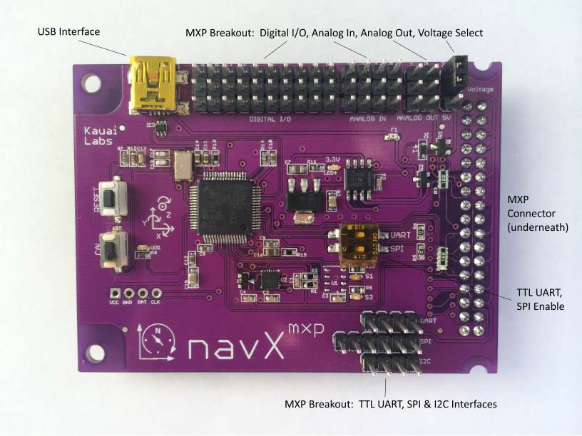
NavX

- Measures acceleration and rotation of robot (6 axes).
- Connects to RoboRIO via pin header.
- Reference
- Works in simulator.
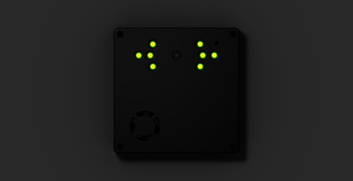
Limelight

- Tracks retroreflective vision targets.
- Includes an LED array for illuminating target and a camera.
- Onboard processor filters out and locates the target. Settings can be configured through a web interface.
- Communicates with RoboRIO over ethernet, using the “NetworkTables” protocol.
- Reference
- Works in simulator, with some configuration.
Feedback loops
Feedback means that the output of a system directly affects the input. For example, the shaft of a motor is connected to an encoder, meaning that the motor output directly changes the encoder input. We can then use the encoder input in our program to change the output of the motor, completing the loop. This is known as “closed-loop” control.
In robotics programming we often use negative feedback loops, which attempt to maintain a state by dampening the stimulus of the input. For example we can use the NavX and drivetrain motors to keep the robot pointed in a direction. When the robot rotates too far in one direction, the code will compensate by running the motors in the opposite direction (negative feedback).
You can read more about “Control Theory” on Wikipedia.
Steps of a feedback loop:
- Establish a “Set Point” (SP) or target value of the sensor
- Repeat continuously while running:
- Read the current sensor value (the “Process Variable” PV)
- Determine the “error” (difference between Process Variable and Set Point)
- Apply a function to the error to determine correction output (with correct sign)
- Update motors or other output devices to correct error
Your Task
- Choose a sensor from the list above.
- Write code that will read some measurement from the sensor and print it continuously to the Driver Station console.
- Deploy and observe how you can change the value of the sensor. What range of values does it produce?
- Come up with a scenario in which a feedback loop might be needed for this sensor.
- Write a feedback loop and test.